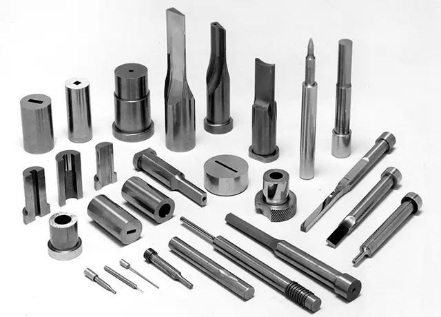
From Material Selection to Manufacturing Best Practices
Cemented carbide wear parts are critical components in industries like mining, oil & gas, and aerospace due to their unmatched hardness, wear resistance, and durability. This guide walks you through the essential steps to design high-performance custom carbide wear parts that meet your application’s exact requirements.
1. Define Your Application Requirements
Before diving into design, clarify:
- Operating Conditions:
- Temperature extremes (-50°C to 1,200°C)
- Contact media (abrasive particles, corrosive fluids, etc.)
- Mechanical stresses (impact, vibration, sliding friction)
- Failure Modes:
- Abrasive wear (e.g., mining drill bits)
- Corrosion (e.g., chemical pump impellers)
- Fatigue failure (e.g., engine components)
Case Study: A mining company reduced downtime by 40% by switching to corrosion-resistant WC-Cr₃C₂-Co alloy for underground machinery exposed to acidic water.
2. Mastering Carbide Material Selection
Key Alloy Components
| Component | Role | Typical Content (%) | Ideal Applications |
|---|---|---|---|
| Tungsten Carbide (WC) | Provides hardness & wear resistance | 80-97 | Cutting tools, drill bits |
| Cobalt (Co) | Binder phase for toughness | 3-20 | High-impact environments |
| Chromium Carbide (Cr₃C₂) | Enhances corrosion resistance | 1-5 | Chemical processing |
| Titanium Carbide (TiC) | Reduces friction coefficient | 1-10 | Bearings, gears |
Grain Size Matters:
- Ultra-fine (<0.5μm): Precision tools (e.g., PCB micro drills)
- Medium (0.5-1.5μm): General industrial applications
- Coarse (>1.5μm): Heavy-duty mining equipment
3. Design Process: 7 Critical Steps
3.1 Geometry Optimization
- Stress Relief:
- Use fillet radii ≥0.5mm
- Avoid sharp edges (opt for R-angle transitions)
- Weight Reduction:
- Incorporate honeycomb or lattice structures
- Maintain uniform wall thickness (±0.1mm tolerance)
Pro Tip: Use ANSYS or SolidWorks Simulation for finite element analysis (FEA) to predict stress distribution.
4. Collaborating with Manufacturers
Technical Documentation Checklist
- 3D CAD models (STEP/IGES format)
- Material specifications (e.g., ISO 4507 Grade K10)
- Tolerance requirements (e.g., ±0.02mm dimensional, ≤0.05mm geometric)
- Surface finish details (e.g., Ra 0.8μm)
Need Expert Help?
Our engineers offer free design reviews and CAD optimization. Contact us today to discuss your project!
5. Common Design Mistakes to Avoid
5.1 Overemphasizing Hardness
- Mistake: Prioritizing hardness over toughness
- Risk: Brittle fracture under impact
- Solution: Adopt gradient structure designs (hard outer layer + tough core)
6. Advanced Manufacturing Techniques
6.1 Additive Manufacturing (3D Printing)
- Advantages:
- Complex internal channels (e.g., spiral cooling ducts)
- 90% material efficiency (vs. 50% for traditional methods)
- Limitations:
- Currently restricted to alloys with <10% cobalt
Ready to Start Your Project?
Request a free consultation to explore:
✅ Custom material selection
✅ 3D printing feasibility
✅ Prototyping services
Conclusion
Designing custom carbide wear parts requires balancing material science, mechanical engineering, and manufacturing expertise. By following this guide and partnering with experienced suppliers, you can create solutions that deliver superior performance and cost efficiency.

